| Airport Cable | |||
![]() 2491X to BS 6004 Cables
2491X to BS 6004 Cables
450/750V PVC Insulated, PVC Sheathed Electric Lock Cables (4 core)
FGD200 07VV-F (CU/PVC/PVC 450/750V Class 5)
APPLICATION
The cables are multicore stranded flexible cables sheathed with thermoplastic PVC compound. The
cables can be offered with the ability to restrict the propagation of the flame in the event of a fire. This
is especially important to slow down the spreading of the fire as the cables may pass from one area
to another within a building. Applications can be found in control and power circuits, power stations,
underground tunnels, lifts, escalators, and high-rise buildings.
STANDARDS
Basic design to BS 6004, BS6500
FIRE PERFORMANCE
FlameRetardance (SingleVerticalWireTest)** |
EN60332-1-2; IEC60332-1-2; BSEN 60332-1-2; VDE0482-332-1; NBN C30-004 (cat.F1);NF C32-070-2.1(C2); CEI 20-35/1-2; EN 50265-2-1*; DIN VDE 0482-265-2-1* |
Reduced FirePropagation(Vertically-mountedbundledwires &cabletest)** |
EN60332-3-24 (cat.C); IEC60332-3-24;BSEN60332-3-24;VDE0482-332-3;NBN C30-004 (cat.F2);NF C32-070-2.2(C1);CEI 20-22/3-4; EN 50266-2-4*; DIN VDE 0482-266-2-4 |
Note:
Asterisk * denotes superseded standard
Asterisk ** denotes that the standard compliance is optional, depending on the oxygen index of the PVC
compound and the cable design.
VOLTAGE RATING
450/750V
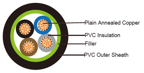
CABLE CONSTRUCTION
Conductor: Plain annealed copper wire, stranded according to BS 6360 Class 5
Insulation: PVC insulation type TI1 to BS 7655
Filler, binder (if any): PP, PET
Outer Sheath: PVC sheath type T6 to BS 7655
COLOUR CODE
Insulation Colour as per BS7671
|
withearth conductor |
withoutearth conductor |
2Cores |
- |
Brown,Blue |
3Cores |
Yellow/Green,Brown,Blue |
Brown,Gray,Black |
4Cores |
Yellow/Green,Brown,Gray,Black |
Brown,Gray,Black,Blue |
5Cores |
Yellow/Green,Brown,Gray,Black,Blue |
Brown,Gray,Black,Blue,Black |
above 5 Cores |
Yellow/Green,BlackNumbers |
Black Numbers |
Outer sheath: Black or as order
Physical AND THERMAL PROPERTIES
Operating temperature: -15º C to +70º C
Short circuit temperature: +160º C
Minimum bending radius: 4x Overall Diameter
Insulation resistance: 20 MΩxkm
CONSTRUCTION PARAMETERS
Conductor |
fGD20007VV-f |
||||||
No.of |
No./ |
Conductor |
Nominal |
Nominal |
Nominal |
Max.DC resistance ofconductor @20°C |
Approx. Weight |
Noxmm2 |
No./mm |
mm |
mm |
mm |
mm |
Ω/km |
kg/km |
4x1.0 |
32/0.20 |
1.32 |
0.6 |
1.0 |
8.4 |
18.1 |
100 |
Electrical PROPERTIES
Conductor Operating Temperature : 90°C
Ambient Temperature : 30°C
Current-Carrying Capacities (Amp)
Conductor |
Reference |
Reference trunkingetc) |
Reference |
Reference |
Reference |
||
Horizontalflat spaced |
Verticalflat spaced |
Trefoil |
|||||
2cables, single- phase |
3 or 4cables, 3-phasea.c. |
2 |
3 or 4cables, 3-phasea.c. |
2cables, single- phase |
3 or 4cables, 3-phase |
2cables, |
3 or 4cables, 3-phase |
2cables, phase |
2cables, |
3
cables, |
|
1 |
2 |
3 |
4 |
5 |
6 |
7 |
8 |
9 |
10 |
11 |
12 |
mm2 |
A |
A |
A |
A |
A |
A |
A |
A |
A |
A |
A |
1.0 |
13 |
- |
- |
- |
15 |
- |
- |
- |
- |
- |
- |
Voltage Drop (Per Amp Per Meter)
Nominal |
2cables d.c. |
2cables, |
3or 4cables,3-phase a.c. |
|||
Ref.Methods3 |
Ref.Methods1 |
Ref.Methods3 |
Ref.Methods1, |
Ref.Methods |
||
11 and12 (intrefoil) |
(Flat and |
|||||
1 |
2 |
3 |
4 |
5 |
6 |
7 |
mm2 |
mV/A/m |
mV/A/m |
mV/A/m |
mV/A/m |
mV/A/m |
mV/A/m |
1.0 |
46 |
46 |
- |
- |
- |
- |